

Arduino LCD display

I'm passionate about coding and enjoy working with embedded systems, app development, and compiler design.
To complete this mini project, you will need the following components:
LCD Display 16x2
Arduino Board
Connecting Wires
Breadboard
Potentiometer
Jumper Wires
Nano Cable
Adder Pins
Steps to Set Up:
Place Components on the Breadboard:
Mount the LCD display on one side of the breadboard.
Place the potentiometer on the same line as the LCD.
Connect the Potentiometer:
Connect one side of the potentiometer to the positive rail (+ve).
Connect the other side to the negative rail (-ve).
Power the LCD Display:
Connect pin 1 and pin 16 of the LCD to the negative rail (-ve).
Connect pin 2 and pin 15 of the LCD to the positive rail (+ve).
This provides power to the LCD display and its backlight.
Adjust the Contrast:
- Connect pin 3 of the LCD display to the center terminal of the potentiometer.
Ground the LCD:
- Connect pin 5 of the LCD display to the ground (negative rail).
Power the Breadboard:
Connect the 5V pin of the Arduino to the positive rail (+ve).
Connect the GND pin of the Arduino to the negative rail (-ve).
Connect Control Pins:
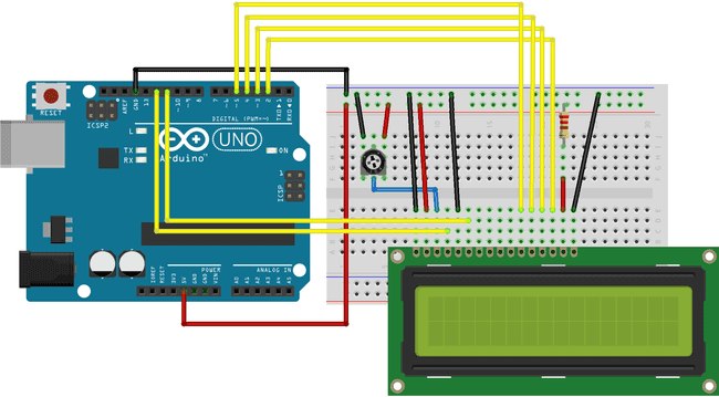
Connect pin 4 of the LCD to pin 12 on the Arduino. This is the register select pin that sends output signals from the Arduino.
Connect pin 6 of the LCD to pin 11 on the Arduino. This is the data enable pin.
Connect Data Pins:
- Connect pins 11, 12, 13, and 14 of the LCD to pins 5, 4, 3, and 2 on the Arduino, respectively.
It should look something like this.

Now install the Arduino IDE into your pc or laptop. Replace the default code with this code.
#include <LiquidCrystal.h>
const int rs = 12, en = 11, d4 = 5, d5 = 4, d6 = 3, d7 = 2;
LiquidCrystal lcd(rs, en, d4, d5, d6, d7);

// to make some custom characters:
byte globe[8] = {
  0b00100,
  0b01110,
  0b11111,
  0b11111,
  0b11111,
  0b01110,
  0b00100,
  0b00100
};

byte smiley[8] = {
  0b00000,
  0b00000,
  0b01010,
  0b00000,
  0b00000,
  0b10001,
  0b01110,
  0b00000
};

byte frownie[8] = {
  0b00000,
  0b00000,
  0b01010,
  0b00000,
  0b00000,
  0b00000,
  0b01110,
  0b10001
};

byte armsDown[8] = {
  0b00100,
  0b01010,
  0b00100,
  0b00100,
  0b01110,
  0b10101,
  0b00100,
  0b01010
};

byte armsUp[8] = {
  0b00100,
  0b01010,
  0b00100,
  0b10100,
  0b01110,
  0b00101,
  0b00100,
  0b01010
};

void setup() {
  // this initialize LCD and set up the number of columns and rows:
  lcd.begin(16, 2);

  // create a new character
  lcd.createChar(0, globe);
  lcd.createChar(1, smiley);
  lcd.createChar(2, frownie);
  lcd.createChar(3, armsDown);
  lcd.createChar(4, armsUp);

  // set the cursor to the top left
  lcd.setCursor(0, 0);

  // Print a message to the lcd.
  lcd.print("Hello "); // when calling lcd.write() '0' must be cast as a byte
  lcd.print(" World ");
  lcd.write(byte(0));
  lcd.write((byte)1);

}

void loop() {
  lcd.setCursor(0, 1);
  // print the number of seconds since reset:
  int x=0;
  x=millis()/1000;
  lcd.print("T:");
  lcd.print(x);
  // read the potentiometer on A0:
  int sensorReading = analogRead(A0);
  // map the result to 200 - 1000:
  int delayTime = map(sensorReading, 0, 1023, 200, 1000);
  // set the cursor to the bottom row, 5th position:
  lcd.setCursor(6, 1);
  // draw the little man, arms down:
  lcd.write(3);
  delay(delayTime);
  lcd.setCursor(6, 1);
  // draw him arms up:
  lcd.write(4);
  delay(delayTime);
  lcd.setCursor(10,1);
  delay(500);
  lcd.write((byte)2);
  delay(500);
  lcd.print("->");
  delay(500);
  lcd.write((byte)1);
}
This code prints Hello World. And it also prints out Custom characters such as the smiling face, globe and a man saying “HI”. There is also a timer which is used to count the number of seconds the program is running for. If you get some error or if the LCD is not turning on then check the connections. It is most likely that some wire is not connected to the right rail.

You can play around with more such programs by going to File>Examples in the app where you will find different programs to play around.
Hope you learnt something new reading this blog. I was board so I tried something new and different.
Happy Coding…


